Hydraulic Torque Wrenches
General Description
- The alkitronic Hydraulic Torque Wrench with the 2 hydraulic hose system for tightening or loosening of heavy bolt connections. The hydraulic pressure to the torque wrench is being converted to a torque via an hydraulic piston. The reaction force can be transmitted to a suitable support point via the insertable reaction absorber (DMA) or directly via the housing (model alkitronic AX). The torque to the hydraulic pump is determined according to the torque chart. The individually pivoting joint couplings (360°, vertical 180°) are convenient, secur, and reliable.
Model Descripton.
- Alkitronic®AT Hydraulic Torque Wrench up to approx. 37.600 Nm* for threads of M 14 and larger. The one-piece, torsion resistant, ergonomically shaped housing is made of high density aluminium. The setting table for the wide torque range ist directly on the tool. The square drive is easily changed from tightening to loosening.
HÌNH.
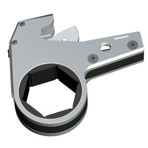
- Alkitronic AX 2-parts torque wrench: up to approx. 49.200 Nm*; developed for applications in restricted space and difficult to access areas; AX drive unit of heavy-duty material; fast changing of the AX hexagon link with extremely small housing radius; drive unit with interchangeable hexagon link from 17 to 145 mm. Trouble-free support without affecting the torque accuracy by lateral force. Drive unit and hexagon link in line, extremely flat and flush design.
HÌNH.
Recommendation: alkitronic® Hydraulic Pumps.
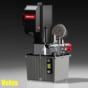
- For fast, reliable operation of the alkitronic® Hydraulic Torque Wrench, we recommend our alkitronic® NOVA or VELOX Hydraulic Pumps. Operating pressure max. 700 bar, can be used worldwide in all mains grids (100-253 V / 45-66 Hz).
Depending on the model, up to 4 hydraulic wrenches can be operated at the same time. Low running costs, robust and compact design, capable of continuous operation. - Without magnetic valve control, the pumps offer high durability equipment and simple automatic operation.
HÌNH.
Alkitronic Accessories.
- Our specific selection of a wide range of accessories, gives you a broader work application field.
- When you need specific, individual solutions, your alkitronic Partner or alki TECHNIK GmbH will gladly advise you.
Alkitronic Accessories for alkitronic AT Hydraulic Torque Wrenches.
- (1) DMA standard reaction arm
- (2) Push button for releasing/locking the drive inserts
Alkitronic AT Drive Pins
- (3) AVS square drive pin
- (4) AIS hex drive pin
Alkitronic Accessories Standard.
- (5) STACO (standard socket)
- (6) STABI (reducer to standard hex drive)
HÌNH
Alkitronic Accessories for Alkitronic AX Convertible Type Torque Wrench.
(1)Link safety pin.
Short“ standard version,
Long“ to use for additional reaction arms.
DMA reaction arms
(2) „extended“ version
(3) „low point“ version
Alkitronic AX Drive Inserts STABI
(4) Reducer to standard hex drive
(5) Reducer to standard square drive
STA
(6) Standard adaptor
Alkitronic STACO
(7) Standard socket.
HÌNH.
Safety Instructions.
Intended use.
- Alkitronic Hydraulic Torque Wrench is designed to tighten or loosen heavy duty bolt connections. Do not use the torque wrench for any other purpose.
Operators responsibilities.
- The operator must have read and understood the instructions in this operation and maintenance manual before using or servicing the alkitronic Hydraulic Torque Wrench. Minimum age of the operator must be 18 years.
- Operation and service may not be performed, if the concerned person does not understand the purpose, consequences, and precise performance of each procedure. For questions regarding the safety measures and areas of application, your alkitronic® Partner will be pleased to assist you.
Placing tool in operation
Control and safety inspection
- The drive inserts/adaptors and reaction arms (DMA) must be correctly fitted and undamaged. Never use damaged parts under any circumstances!
- Use original alkitronic® spare parts only!
- Adapter or socket sizes must correspond exactly to the size of the nut or the screw.
- Couplings, nipples of the Torque Wrench and hydraulic hoses must be connected properly.
- Local regulations for the working environment and for the hydraulic hoses must be complied with.
Preparing for bolting – alkitronic AT
Finishing with square drive inserts. Example alkitronic STACO (standard socket)
- First, prepare the torque wrench for the chosen rotating direction (tightening or loosening). Place the AVS Standard Square Drive Pin (1) in the chosen position (replacement of the AVS, see 3.4). The rotation direction is indicated by the torque wrench housing.
- NOTE: For a direction change, the square drive insert is being changed from one side of the torque wrench to the other side.
HÌNH
- Next place the alkitronic STACO (2) on the square drive. Insert the safety pin and secure it with the rubber ring.
HÌNH.
Positioning DMA (Reaction arm).
Press the safety button down (3) and remove the DMA from the external toothing. Insert the DMA completely in the chosen position into the toothing (locking device must be engaged).
HÌNH.
Support of reaction moment / Support points.
Place DMA vertical and parallel to the axis of the bolt resp. socket/adaptor.
HÌNH.
Replacement of square drive or other drive inserts.
- An exchange will be necessary to change the rotating direction or damaged drive inserts (e.g. square drive AVS) with other drive inserts from our accessories program.
Models AT: The push button (1) must be pressed to change the drive square.
HÌNH.
Procedure:
- Press the push button (1) and hold it down. Pull the square drive (2) out of the housing. Remove the push button.
- After the exchange, put it together in the reverse order and secure the square drive (2) with the push button (1) again.
- Check that the push button is firmly connected to the insert.
HÌNH.
Preparing for bolting – alkitronic AX
Assembling the alkitronic AX.
- Select the AX hexagon link (1) corresponding to the joint. Make sure the hexagon link is suitable for the drive unit (2). Do not use the hexagon links of any other tools.
- Push the AX drive unit without twisting into the hexagon link up to the stop. By inserting the standard link bolt (3) completely both parts of the tool are firmly connected and secured.
HÌNH
Changing the hexagon link.
- Remove the link bolt (3) and pull the drive unit out (2) from the hexagon link.
- Assembly as described above.
- NOTE: To reduce the spanner width, an optional alkitronic STA (5) can be used in the hexagon link drive.
HÌNH.
Setting the rotation (tightening/loosening).
- The rotation is changed by reversing the alkitronic® AX Torque Wrench by 1800. The bolting direction is marked at the housing of the hexagon link.
HÌNH.
Support of reaction moment / Support points.
- Place the reaction surface (1) of the AX hexagon link (Fig. 3)against an adjacent nut, flange or solid system component.
HÌNH.
Support position correct/incorrect alkitronic AX.
Description of supports Fig. 4:
HÌNH.
Positioning the DMA – alkitronic AX (option)
- Depress the short standard link bolt (3) and insert the DMA (6) correctly. Then attach the longer link bolt (7) to secure the DMA with the AX drive unit and the AX hexagon link.
HÌNH.
- Depending on the application a DMA (Extended Reaction Arm, Fig. 5) can also be used.
HÌNH.
Operation.
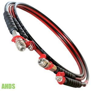
Connecting hydraulic hoses.
- The nipple at the two-hose-system is the connection for Advance (A). The coupling is the connection for Return (R).
- Original alkitronic hoses, couplings and hydraulic power units are designed to guarantee a correct connection.
HÌNH.
Starting procedure hydraulic power unit.
Procedures
- when first putting the tool into operation.
- when changing torque wrenches at the hydraulic unit.
General description tightening/loosening.
- Set hydraulic power unit in operation according to the operation manual.
- Carry out pressure adjustment at the hydraulic power unit according to torque chart of the alkitronic® Hydraulic Torque Wrench (see example page 12 above, Fig. 4).
- Activate the torque tool a couple of times before connecting to bolt/nut to ventilate hoses and the tool, if necessary. Make sure function is faultless.
- Connect the torque wrench with the bolt/nut and start the bolting process. The reaction surface (AX hex link) or the reaction arm (DMA) of the torque wrench will move against the support point and the bolt/nut will begin to turn.
- Keep pressing the remote control button of the hydraulic
pump until the drive of the alkitronic® AT or AX stops turning. The pre-set pressure is reached. - Then press the remote control button one or two times. Make certain the final torque is transmitted to the bolt connection and the tool does not stop until it reaches the end stop of the hydraulic piston.
- Watch the pressure gauge display to make certain the preset pressure is reached.
HÌNH.
Ending or Interrupting the Work. (Also with accessories change)
- Break off tool pressure by turning off the hydraulic power unit to avoid unintended operation.
- Do not lift or carry the alkitronic® Hydraulic Torque Wrench by the hoses.
- Remove quick-lock couplings at the hydraulic power unit, when finishing operation.
Functional and Operational Tests.
Optical inspection.
- Check all connections (nipples/couplings) for proper condition.
Tightness and contamination.
- Check all: tool, high-pressure hydraulic hoses, and all connections for integrity and possible replacement or cleaning.
- Contamination in the hydraulic system will cause malfunctions and operating failure.
- Check hydraulic components for tightness. Defective components must be replaced professionally.
Specialist inspection.
- The alkitronic® Hydraulic Torque Wrench is an extremely powerful and robust tool. Nevertheless to ensure performance for years regular maintenance of the alkitronic Hydraulic Torque Wrenches is necessary. Maintenance must be performed by authorized personnel according to legal regulations.
- For safety reasons all hydraulic hoses used in regular requirements must be replaced at the latest after five years (additionally max. two years storage). After increased requirements (multiple shifts, short cycle times, hand tools) replace the hoses after two years.
Service / Storage / Maintenance.
- Alki TECHNIK GmbH provides usable spare parts sets for maintenance or replacement by authorized personnel. Parts lists with sectional tool drawings are also available. Please contact your alkitronic Partner.
Lubrication.
- Keep all movable parts, gliding surfaces, bearing surfaces, multi-axis swivels etc. clean and lubricated in order not to reduce the life of the tool. Dirt or corrosion affect tool performance adversely. See page 13, Lubrication points Fig. 5.
HÌNH
Recommended lubrication: Liqui Moly Marine (Liqui Moly Boots Grease)
Maintenance periods:
- Upon continuous operation every 20 hours.
- Improper lubrication may undermine torque accuracy
Storage:
- Always store the dry, clean alkitronic Hydraulic Torque Wrench in its transportation case or in any lockable box. Moisture leads to oxidation on both housing and interior parts. As a result malfunction and further damages may occur.
- For storage, make sure the hydraulic hoses are disconnected and that the ends of the hose lines and the connecting components (couplings/nipples) are plugged with protecting caps.
- Store the hydraulic hoses in a cool, dry, and dust-free location.
- Avoid direct solar and UV radiation, ozonegenerating lighting (i.e. fluorescent sources of light, mercury vapor lamps), and storage temperatures below -10°C.
Technical Notes.
To avoid faulty bolted joints or motor damage, observe the
following:
- Oil temperature must not exceed 65 °C.
- Regularly check oil level and oil condition on pump reservoir.
- Regularly check the accuracy of the gauge with a testing
manometer
Technical Data
HÌNH
| Model | AT 1 | AT 2 | AT 3 | AT 5 | AT 8 | AT 10 | AT 20 | AT 25 | AT 30 | AT 50 |
| Height H2 mm | 108,1 | 131 | 176,5 | 199 | 217 | 232 | 270 | 297 | 332 | 341 |
| Lenght L1 mm | 110,8 | 144,5 | 178 | 210,5 | 222 | 245,5 | 307,5 | 323 | 372,5 | 400 |
| Lenght L2 mm | 139,3 | 173 | 229 | 270,5 | 293 | 317,5 | 383,5 | 401 | 496,5 | 516 |
| Radius R mm | 20,5 | 26 | 34 | 39 | 47 | 51 | 59 | 66 | 77 | 81 |
| Radius R2 mm | 68,3 | 85 | 114 | 137 | 153 | 154 | 186 | 199 | 214 | 259 |
| Width B1 mm | 42 | 50 | 68 | 80 | 90 | 100 | 120 | 137 | 153 | 160 |
| Width B2 mm | 54 | 66,5 | 89,5 | 100 | 120 | 128 | 153 | 159,5 | 167 | 178 |
| Weight (approx.) kg mm | 1,8 | 2,5 | 5 | 8 | 11 | 15 | 26,5 | 35 | 50 | 87 |
| Type | AX 1 | AX 2 | AX 4 | AX 8 | AX 16 | AX 32 *** | |
| Torque range (approx.) * | Nm | 60-770 | 260-2600 | 540-5400 | 1150-11900 | 2150-22900 | 4450-49000 |
| lbf.ft | 45-560 | 192-1928 | 395-3950 | 830-8630 | 1560-16600 | 3220-35650 | |
| Hexagon | AF ** mm | 14-32 | 27-55 | 36-70 | 55-95 | 80-115 | 95-145 |
| Radius (approx.) from-to | R mm | 19-25 | 26-42 | 34-52 | 46-79 | 63-87 | 82-109 |
| Width | B mm | 24 | 38 | 47 | 58 | 70 | 92 |
| Length | L mm | 111 | 167 | 203 | 253 | 330 | 390 |
| Height | H mm | 83 | 103 | 144 | 180 | 194 | 278 |
| Weight (approx.) | kg | 1 | 2.5 | 5.18 | 10.7 | 16.5 | 25 |
Hydraulic Torque Wrenches
Showing all 4 results
-
Hydraulic Torque Wrenches
Hydraulic torque wrench, low profile tightening or loosening heavy bolt
Hydraulic torque wrench with two hydraulic hose system for tightening or loosening heavy bolt connections. alkitronic® AX convertible type torque wrench up to 49,000 Nm. Drive element with interchangeable hexagon link from 14 to 145 mm.
SKU: H-AX -
Hydraulic Torque Wrenches
VELOX Electric Hydraulic Pump for torque wrenches – Alkitronic
VELOX electric hydraulic pump is a robust, long-life quality product made in Germany. Protection class IP65) is protected against rain, splash water and dust deposit to eliminate costly downtime. Its suitable for 110V or 230V. Alkitronic.
SKU: Velox