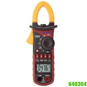
Digital multimeter IP44 with solar charger
Available on backorder
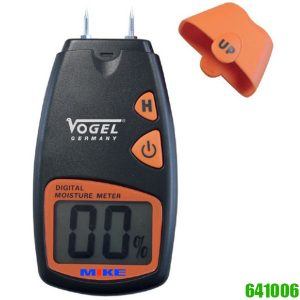
Housing is made of tough, demage-resistant ABS-plastic, dustproof and spray water resistant. Large LCD display clear reading, digit height 19 mm, current DC and AC up to 20 A. Made in Germany.
Available on backorder
640384 electric digital multimeter IP44 with solar charger on top of instrument
– Very useful instrument, especially in the field of electrical engineering
– Housing is made of tough, demage-resistant ABS-plastic, dustproof and spray water resistant
– Large LCD display clear reading, digit height 19 mm
– Current DC and AC up to 20 A
– Incl. thermo probe for temperature measurements
– Diode test, transistor test function, conductivity test, with acoustical signal
– With battery test function
– With frequency function
– With decimal digits change
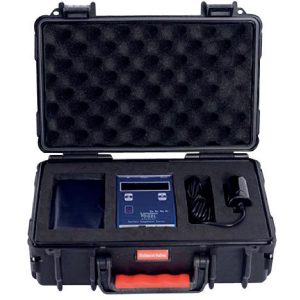
– Incl. 2x measuring lines and readiness bag
– Incl. rechargeable accu and charger cable, with operation manual
Features
- LC-Display
- SELECT key
- Hz/DUTY Key
- HOLD / backlight key
- Max/Min key
- REL key
- RANGE key
- Rotary Switch
- Saler charger
- V / 10A /mA / COM input Jack
General Specifications
- Max Voltage between input terminal and Earth Ground: CAT IV 600V
- Over-range indication: display “OL” for the significant digit
- Automatic display of negative polarity “_”
- Low Battery indication: displayed
- Max LCD display: 6000 digits, capacitor, frequency range: 9999 digits
- Auto ranges
- Fuse protection: F-800mA/1000V (Ø6x32mm) F-10A/1000V (Ø10x38mm)
- Power supply: 6F22 9V battery for 90B; 3.6V Ni-MH Battery for 90BS
- Green Power: Solar charger only 90BS
- Auto power-off: 15 minutes, Push SELECT Key, Auto Power Off disable
- Operating Temp.: 0°C to 40°C (relative humidity <85%)
- Storage Temp.: -10°C to 50°C (relative humidity <85%)
- Guaranteed precision Temp.: 23±5 °C (relative humidity <70%)
- Dimension: 193x88x41mm; Weight approx. 320g (including battery)
Testing Specifications
Accuracy is specified for a period of year after calibration and at 18°C to 28°C (64°F to 82°F) with relative humidity to 70%
DC Voltage
| Range | Resolution | Accuracy |
| 600mV | 0.1mV | ± (1.2% of rdg +5 digits) |
| 6V | 1mV | ± (0.8% of rdg +5 digits) |
| 60V | 10mV | ± (0.8% of rdg +5 digits) |
| 600V | 100mV | ± (0.8% of rdg +5 digits) |
| 1000V | 1V | ± (1.5% of rdg +10 digits) |
Input Impendence: 10 MΩ, 60mV, 600mV range >100MΩ
Overload protection: DC 1000V or AC 750V
AC Voltage (True RMS)
| Range | Resolution | Accuracy | Sensitivity |
| 600mV | 0.1mV | ± (2.5% of rdg +15 digits) | 40HZ-1KHZ |
| 6V | 1mV | ± (1.0% of rdg +10 digits) | 40HZ-400HZ |
| 60V | 10mV | ± (1.0% of rdg +10 digits) | 40HZ-400HZ |
| 600V | 100mV | ± (1.0% of rdg +10 digits) | 40HZ-400HZ |
| 750V | 1V | ± (1.0% of rdg +10 digits) | 40HZ-400HZ |
Input Impendence: > 10 MΩ, 60mV, 600mV range >100MΩ
Overload protection: DC 1000V or AC 750V
DC Current
| Range | Resolution | Accuracy |
| 600uA | 0.1µA | ± (1.0% of rdg +5 digits) |
| 6000uA | 1µA | ± (1.0% of rdg +5 digits) |
| 60mA | 10µA | ± (1.0% of rdg +5 digits) |
| 600mA | 100µA | ± (1.0% of rdg +5 digits) |
| 6A | 1mA | ± (1.5% of rdg +5 digits) |
| 10A | 10mA | ± (1.5% of rdg +5 digits) |
Overload protection
6A & 10A ranges: 10A/1000V fuse, 10A up to 10 seconds; F500mA/1000V fuse for other ranges
AC Current
| Range | Resolution | Accuracy |
| 600uA | 0.1µA | ± (1.5% of rdg +10 digits) |
| 6000uA | 1µA | ± (1.5% of rdg +10 digits) |
| 60mA | 10µA | ± (1.5% of rdg +10 digits) |
| 600mA | 100µA | ± (1.5% of rdg +10 digits) |
| 6A | 1mA | ± (2.0% of rdg +10 digits) |
| 10A | 10mA | ± (2.0% of rdg +10 digits) |
Overload protection
6A & 10A ranges: 10A/1000V fuse, 10A up to 10 seconds; F800mA/1000V fuse for other ranges
Frequency Range: 40 to 1KHz
Resistance
| Range | Resolution | Accuracy |
| 600Ω | 0.1Ω | ± (1.2% of rdg +10 digits) |
| 6KΩ | 1Ω | ± (1.2% of rdg +5 digits) |
| 60KΩ | 10Ω | ± (1.2% of rdg +5 digits) |
| 600KΩ | 100Ω | ± (1.2% of rdg +5 digits) |
| 6MΩ | 1KΩ | ± (1.5% of rdg +10 digits) |
| 60MΩ | 10K | ± (2.5% of rdg +10 digits) |
Overload protection: 600V effective value
Capacitor
| Range | Resolution | Accuracy |
| 9.999nF | 0.001nF | ± (3.0% of rdg +20 digits) |
| 99.99nF | 1pF | ± (2.5% of rdg +10 digits) |
| 999.9nF | 0.1nF | ± (2.5% of rdg +10 digits) |
| 9.999µF | 1nF | ± (2.5% of rdg +10 digits) |
| 99.99µF | 10nF | ± (3.0% of rdg +10 digits) |
| 999.9µF | 0.1µF | ± (3.0% of rdg +25 digits) |
| 9.999mF | 1µF | ± (3.0% of rdg +25 digits) |
| 99.99mF | 10µF | ± (3.0% of rdg +25 digits) |
Overload protection: 600V effective value
Frequency Testing
| Range | Resolution | Accuracy |
| 9.999Hz | 0.001Hz | ± (0.5% of rdg +15 digits) |
| 99.99Hz | 0.01Hz | |
| 999.9Hz | 0.1Hz | |
| 9.999kHz | 1Hz | |
| 99.99kHz | 10Hz | |
| 999.9kHz | 100Hz | |
| 9.999Mhz | 1kHz |
Overload protection: 600V DC or rms AC, Sensitivity: Range of input voltage:1.5V-10V, if input voltage over range, need adjust
Temperature (NiCr-NiSi sensor)
| Range | Resolution | Accuracy |
| -4-1832°F | 1°F | ± (3 of rdg +5 digits) |
| -20-1000°C | 1°C | ± (3 of rdg +5 digits) |
Overload protection: 600V DC or rms AC
Diode Test
| Range | Resolution | Accuracy |
| 1mV | Display: read approximate forward voltage of diode |
Overload protection: 250 effective value, forward DC current: approximate 1.5mA
Reversed DV voltage: approximate
Continuity
| Range | Function |
| Built-in buzzer will sound if resistance is lower than 50Ω |
Overload protection: 250V effective value
Open circuit voltage: approximate 1.0V
Battery Power Test
| Range | Accuracy | Test Condition |
| ± (1.5% of rdg +5 digits) | Loading Current Approx. 25mA |
Overload protection: DC/AC PEAK 15V
Functions:
| Description | |
| LCD Display | 6000 digits, full function symbol display |
| SELECT key | This key work on the “CAPΩ” range, Push the key to choose resistance, diode, continuity test, on the voltage or current range, change to DC/AC, and °C/°F range, change to °C/°F; if press and hold SELECT key to power on, Auto Power Off function will be disabled. |
| Hz/DUTY Key | In “ACV/ACA” or “Hz” range, push the key, you can measure the Hz, push again, can measure the duty. |
| HOLD/back Light key | In any range, push the key, the present display value will be locked and the “H” symbol will appear, push it again to exit HOLD and the “H” symbol disappear. Press “HOLD” button more than 2 seconds, the backlight will light, press it more than 2 seconds again, the backlight will light off. |
| MAX/MIN key | Push the key to select MAX mode, push it again to change MIN mode, push once again to change max-min, press the key for more than 2 seconds to go back auto range mode. |
| REL Key | Pressing this button, the meter enters relative measuring mode, “REL” is displayed on the LCD and the present reading becomes the reference value and displayed on the display. Relative measurement REL = measurement value Reference value. |
| RANGE key: | Pressing this button, the meter enters manual range mode, press it more than 2 seconds again, return to auto mode. |
| Rotary Switch: | Use this switch to select functions and ranges. |
| Input Jack | Switch to V / 10A /mA / COM Input Jack |
Special Cautions for Operation
- The meters can be safe only according to standard procedures when used in conjunctions with supplied test leads. To replace damaged test leads with only the same model or same electric specifications.
- To avid risk of electric shock, do not use the meters before the cover is in place.
- The Rotary switch should be right position for the testing.
- To avoid electric shock and damaging the instruments, the input signals are forbidden to exceed the specified limits.
- When measuring TV set or switched power, attention should be paid to the possible pulses that may bring destruction to the circuit.
- Rotary switch position is forbidden to be changed at random during measurement.
- Take caution against shock in the course of measuring voltage higher than DC 60V & AC 30V.
- Protection fuse should be replaced only with same type and same specification.
- After operation is finished, set function switch at OFF range to save battery power.
- If the meter is without usage for long time, take out battery to avoid damage by battery leakage.
Operating Instructions
Measuring DC Voltage
Step 1: Connect the black test lead to COM jack and the red to VHz jack.
Step 2: Set the rotary switch at the desired V range position.
Step 3: Connect test leads across the source or load under measurement.
Step 4: You can get reading from LCD. The polarity of the red lead connection will be indicated along with the voltage value.
Note:
- When only ‘OL’ is displayed, it indicates over-range situation.
- “” means you can’t input the voltage more than 1000V, it’s possible to show higher voltage,
But it may destroy the inner circuit or pose a shock. - Be cautious against shock when measuring high Voltage.
Measuring AC Voltage
Step 1: Connect the black test lead to COM jack and the red to VΩHz jack.
Step 2: Set the rotary switch at the desired V ~ range position.
Step 3: Connect test leads across the source or load under measurement.
Step 4: You can get reading from LCD.
Note:
- When only ‘OL’ is displayed, it indicates over-range situation.
- “” means you can’t input the voltage more than 750V, it’s possible to show higher voltage,
But it may destroy the inner circuit or pose a shock. - Be cautious against shock when measuring high Voltage.
Measuring DC & AC Current
Step 1: Connect the black test lead to COM jack and the red to the µAmA jack for a maximum 600mA current, for a maximum 6A or 10A current, move the red lead to the 10A jack.
Step 2: Set the rotary switch at the desired uA & mA & 10A range position, it shows symbol for testing DC current, if you want to test AC current, push ‘select’ button switch.
Step 3: Connect test leads in series with the load under measurement.
Step 4: You can get reading from LCD. The polarity of the red lead connection will be indicated along with the DC current value.
Note:
- When only ‘OL’ is displayed, it indicates over-range situation.
- “” means the socket mA’s maximum current is 600mA and 10A’s maximum current is 10A, over current will destroy the fuse.
Measuring Resistance
Step 1: Connect the black test lead to COM jack and the red to VΩHz jack.
Step 2: Set the rotary switch at the desired range position.
Step 3: Connect test leads across the resistance under measurement.
Step 4: You can get reading from LCD.
Note:
- For measuring resistance above 1M, the mete may take a few seconds to get stable reading.
- When the input is not connected, i.e. at open circuit, the figure “OL” will be displayed for the over-range condition.
- When checking in-circuit resistance, be sure the circuit under test has all power removed and that all capacitors have been discharged fully.
Measuring Capacitor
Step 1: Connect the black test lead to COM jack and the red to -II- jack.
Step 2: Set the rotary switch at the desired range position.
Step 3: Connect test leads across the resistance under measurement.
Step 4: You can get reading from LCD.
Caution:
- Capacitors should be discharged before being tested.
- When testing large capacitance, it will take about 4-7 seconds.
- When testing small capacitance (1uF), to assure the measurement accuracy, first press “REL”, then go on
measuring. - Max. input over-load: 600V rms<10sec
Measuring Frequency
- Connect the black test lead to COM jack and the red to Hz jack.
- Set the rotary switch at the Hz range position.
- Connect test leads across the source or load under measurement.
- You can get a reading from LCD.
Temperature measurement
- Connect the black test lead of the sensor to T- socket and the red test lead to the “T+” socket.
- Set the selector switch to “C/°F” position.
- Put the sensor probe into the temperature field under measurement.
- Read the result from the LCD panel.
Note: Max. input over-load: 250V rms<10sec
- The temperature function shows the random number at ordinary times, must insert the thermocouple in temperature
test hole while examining temperature. - This meter in closure WRNM-010 type contact thermocouple limit temperature is
- 250 °C (300°C shortly).
- Please don’t change the thermocouple at will, otherwise we can’t guarantee to measure accuracy. Please don’t importing the voltage in the temperature function.
- Please use special probe for test high temperature
Diode Testing
- Connect the black test lead to COM jack and the red to jack. (the polarity of red lead is “+”)
- Set the rotary switch at the Ω range position, push “SELECT” button switch until symbol of is displayed on LCD.
- Connect the red lead to the anode and the black lead to the cathode of the diode under testing.
- You can get a reading from LCD.
Note:
- The meter will show approximate forward voltage drop of the diode.
- If the lead connection is reversed, only “OL” will be displayed.
Continuity Testing
- Connect the black test lead to COM jack and the red to jack.
- Set the rotary switch at the Ω range position, push “SELECT” button switch until symbol of is displayed on LCD.
- Connect test leads across two points of the circuit under testing.
- If continuity exists (i.e. resistance less than about 50+++), built-in buzzer will sound.
Note:
- If the input open circuit, the figure “OL” will be displayed.
- Circuit under measurement should be power-off, otherwise, any load signal can make the buzzer sound
Battery Power Test
- Set the FUNCTION switch to the “” range.
- Connect the BLACK test lead to “COM” jack and the RED test lead to the “VΩ” jack.
- Connect the BLACK test lead to the cathode and the RED test lead to the anode of the battery under testing.
- The LCD display Voltage of battery by testing with load.
Recharge Function
- Provide sun light is enough, Solar charger is working away whether ON or OFF.
- When low battery, set function witch at “OFF” position.
- Connect the red lead of special recharge wire to VΩHz jack and the black lead to the COM jack.
- Connect the USB plug of special recharge wire to USB socket of computer ON or charger of the meter special.
Maintenance
- Before attempting to remove the battery door or open the case, be sure that test leads have been disconnected from measurement circuit top avoid electric shock hazard.
- To avoid electrical shock, remove test leads from measurement circuits before replacing the fuse. For protection against fire, replace fuses only with specified ratings: F-800mA/1000V fuse or F-10A/1000V.
- You must replace the test leads if the lead is exposed, and should adopt the leads with the same specifications as origin.
- Use only moist fabric or small amount of detergent but not chemical solution for cleaning.
- Do not use the meter before the back cover is properly closed and screw secured. Upon any abnormality, stop
operation immediately and send the meter for maintenance. - Please take out the battery when not using for a long time.
Safety Information
- The meters are designed according to IEC-1010 concerning electronic measuring instruments with an over-voltage category 600V (CAT IV) and pollution 2.
- Follow all safety and operating instructions to ensure that the meter is used safely and is kept in good operating condition.
- Safety symbols:
Important safety information, refer to the operating manual.
Dangerous voltage may be presence.
Double insulation (protection Class II).
Please note:
– Please prepare measuring very carefully. The device should be regularly cleaned with cotton-cloth.
– Do not use petrol. Do not expose the device direct to the sun light, ultraviolet rays or extreme temperatures.
– Prevent it from any shock and do not immerse the device in any liquid.
– Electric etching or engraving by high voltage can destroy the electronic chip, no guarantee will be given!
– Never dismantle the instrument housing. The battery should be taken out, if no use for a long time.
– Do not give used batteries in refuse. Please give it to a special collecting depot.
– Declaration of conformity and confirmation of traceability:
We declare under our sole responsibility that this product is in conformity with standards and technical data as specified in our sales documents (operation instructions, leaflet and catalogue).
We certify that the measuring equipment used to check this product, and guaranteed by our Quality Assurance, refers to national standards. Thank you very much for your confidence in purchasing this product.